I used 8 AWG THNN wire from the battery in the front tongue box back to the fuse panel in the back galley, and 14 AWG THHN wires for all the run from the fuse box to each component (light, fan, 12 volt socket, etc). To avoid problems each component was wired separately from the fuse box and back. This allowed for splices to be isolated at the fuse box, battery, or the component itself in order to avoid potential issues in the future with broken connections within the walls that would be inaccessible. Black and red wires were used to help me keep hot and ground straight.
Aside from the 12 volt system, I had a separate system for the trailer lights (side indicator, tail, break), that had to be wired as well. These were wired similarly with individual runs to to each light that met back above the galley electrical compartment so all splices could be localized. From there a group of wires were then run to the front of the trailer into the tongue box.
First of all I ran all the wires to I would need to get the length for each run before I drilled any holes.
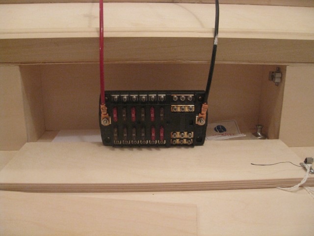
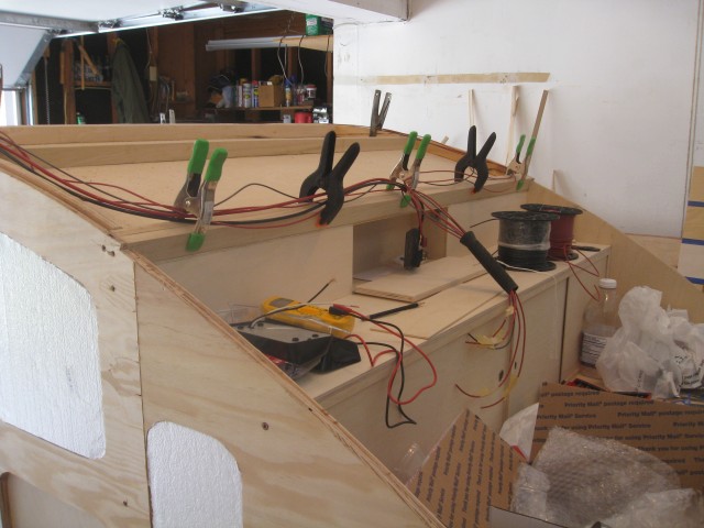
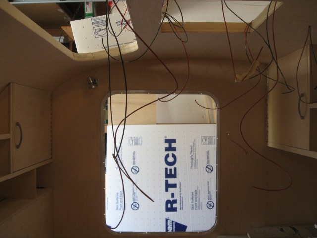
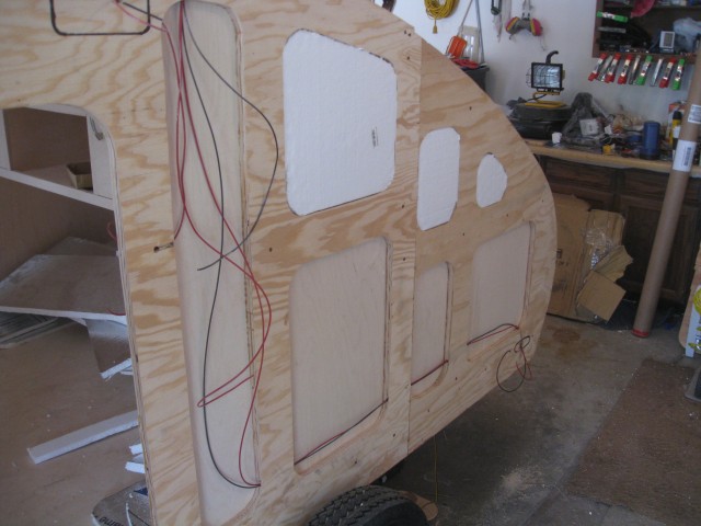
I glued in a backing plate so I could mount the cabin dome light.
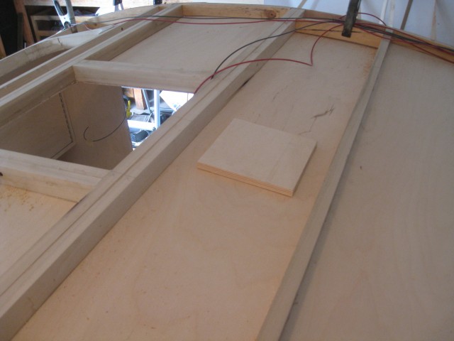
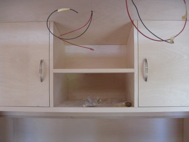
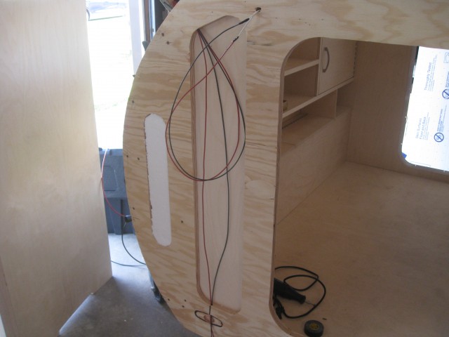
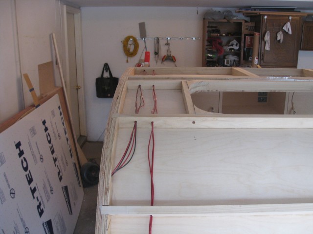
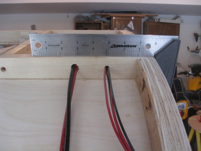
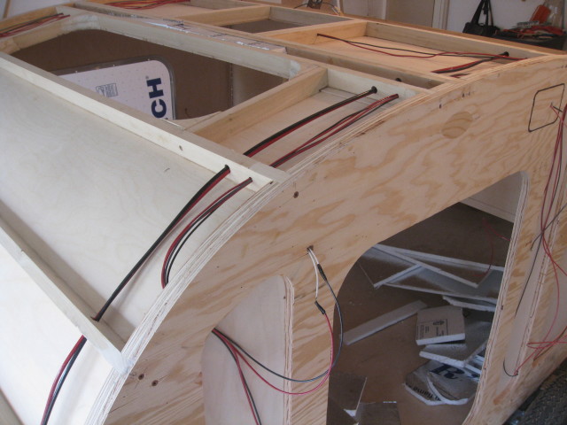
Once I found out the lengths all all the wire runs I drilled the wiring channels through the roof spars. The left channel contains the main positive and ground wires from the battery, and on the right are the component wires.
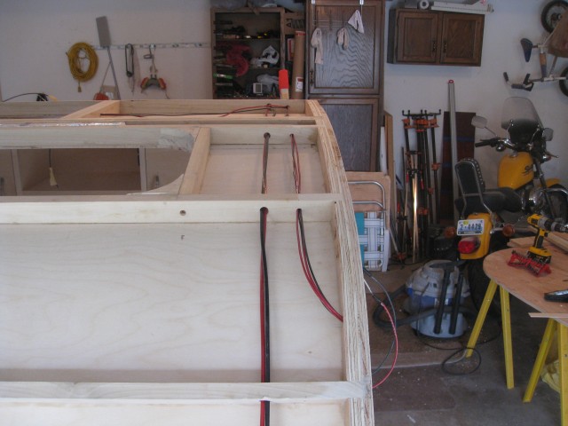
Similarly the left wires are components and to the right are the trailer lights.
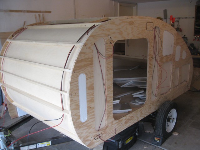
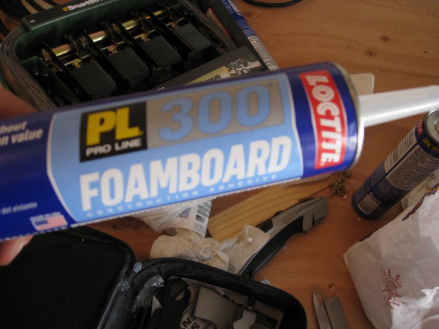
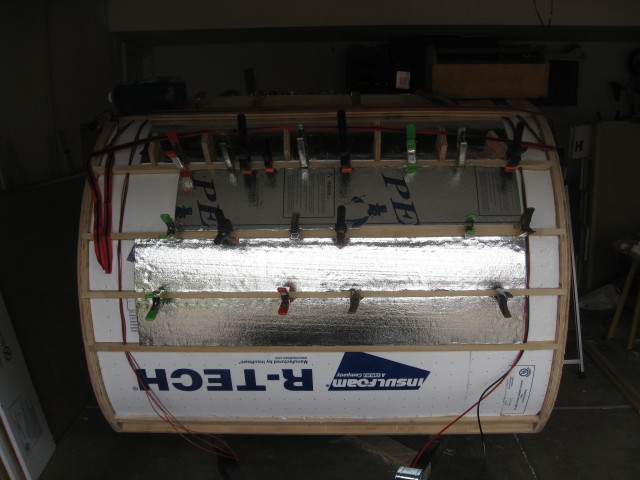
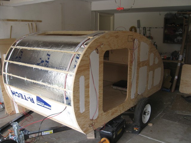
With the wires run I re-installed the insulation in the walls, and began installing the insulation in the roof. The roof has 2 layers of 3/4″ insulation with the wires running between them. The insulation was secured with PL 300 Foamboard adhesive.
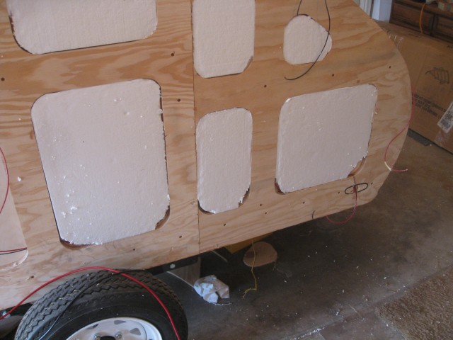
Clamps and blocks were used to hold the insulation in place until the adhesive cured.
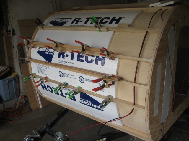
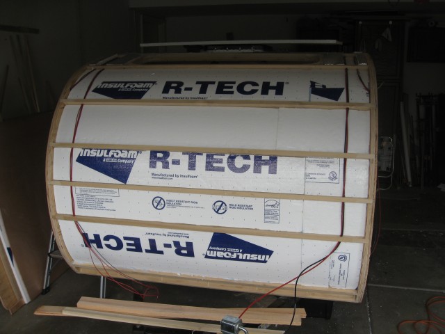
The second layer in installed facing outward, and channels were created to allow passage of the wires.

<span class="dsq-postid" data-dsqidentifier="1624 http://teardropbuilder.com/?p=1624">12 Comments
Looking at your pictures and descriptions I can’t quite tell, did you keep the wiring for the running/brake lights entirely separate from the 12V system running off the battery in the tongue box? Specifically, are the running/brake lights powered by your tow vehicle via a wiring harness?
Yes they are completely separate. The running lights plug into a wiring harness on the tow vehicle, and the connector trailer side originates from the tongue box.
The last three images of this page load image 6227. I was given a trailer this week and found your page. My electrical experience is low. I’d like to know what the controller with the LED screen is in the last picture. Make and model, then I can Google it’s purpose/integration. It looks like a power reading instrument … ? Thanks for the amazing information on the page.
It’s a Turnigy Watt Meter, a fantastic piece of equipment. It displays a wide variety of power stats including current/Max Amp usage, Voltage, Amp/Hr used since power on, etc. I can get a pretty good picture of the overall battery charge by looking at the current voltage.
http://hobbyking.com/hobbyking/store/__75944__Turnigy_180A_Watt_Meter_and_Power_Analyzer.html?strSearch=turnigy%20watt
Good luck on your new trailer!
Great trailer! Can I ask where you got your fuse panel from?
Thank you!
The Fuse block is a Blue Sea Systems 5026 Fuse Block w/cover. I ordered it on Ebay for $45.
Thanks! The Blue Sea stuff looks pretty good, I think I’ll be using them in the future. Cheers!
Ryan, I may have missed it in your write up, but how did you drill those wire runs into the walls? Did you already have the inside skins on when you drilled them? I ask because I am considering the clearance issues of a typical drill and how to go about making those holes in such a tight spot. Example…the tail light run at the bottom that runs between three foam panel cutouts.
Good question! I did my dry fit of the wall panel before applying the inner skins and marked where all the lights and wires should go. At this point you can take down the walls and get a drill in there to drill all your wiring runs. When you are doing this step take the time to account for the number of wires and their width and test that they all fit as expanding the holes once the inside skins are on is very difficult.
If (like me) you missed doing this, you can also just route a channel, and either cover it up, or leave it to be covered up by the outer skin.
Ryan,
I’m almost finished! What is the rocker switch on the interior used to turn on/off? It seems like all of the components have their own on/off switches, so I was just curious what I should splice to those switches.
They turn on/off the outside door lights from the inside. Makes things easier in the middle of the night and you want to take a peek outside.